Status: Completed Successfully on 2/28/2023
In for repair is a front-loading NES with NESRGB mod that no longer outputs a picture. The console power light comes on, so I opened it up to have a look.
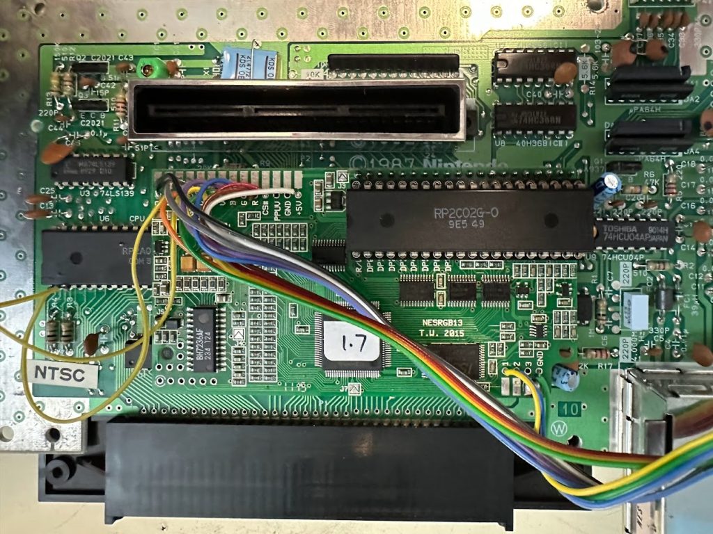
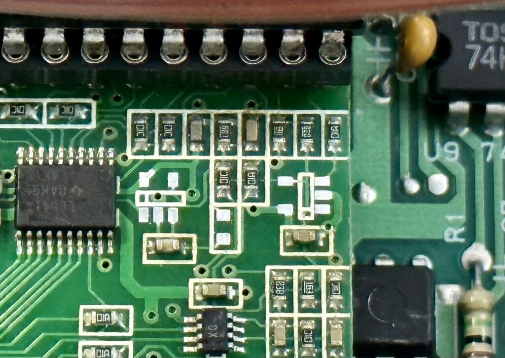
At first glance, everything looks fine, but looking closer at the PPU …
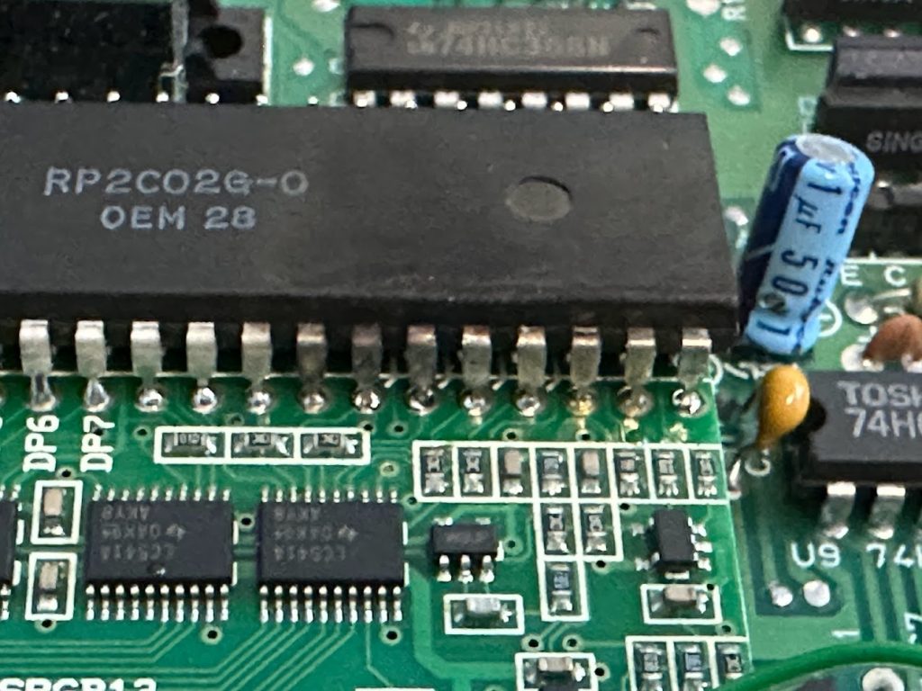
The PPU looks burnt and melted in the lower-right corner. Not good.
Normally the PPU is installed in a socket that’s included in the NESPPU kit, so swapping in another PPU for testing would be easy. Unfortunately whoever installed this mod kit before me decided to solder the PPU directly to the mod board instead.
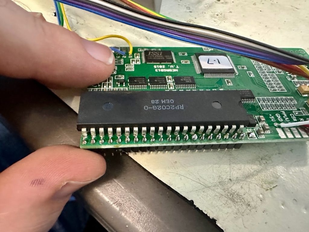
That also meant that the PPU was covering up some of the male pin headers on the underside of the mod board, so it wasn’t sitting flush.
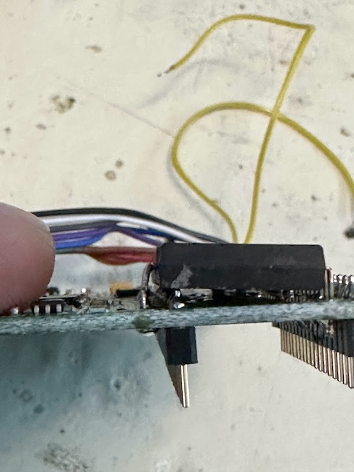
Seems like a lot of hassle to save on the cost of a socket IMHO. Anyway, I ended up chopping out one side of the PPU legs and desoldered the male pin header on the other side of the PPU to finally get it removed from the mod board.
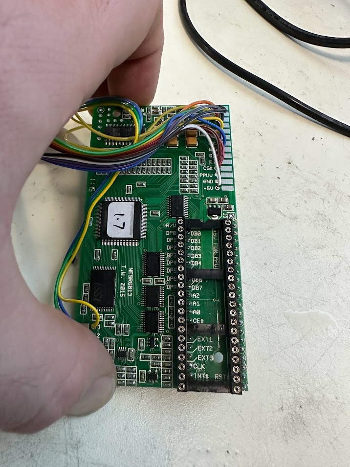
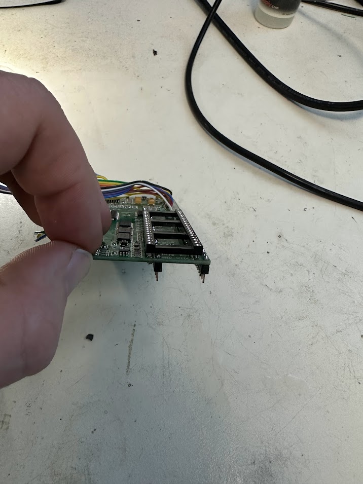
I then installed a socket for the PPU and a fresh set of male pin headers.
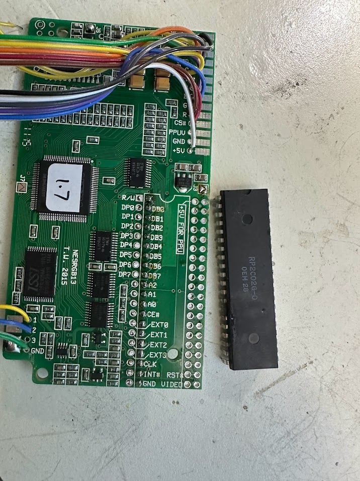
A replacement PPU was available for purchase from Ebay for $35 and the console’s owner agreed to the fee. I placed the order and it arrived a few days later.
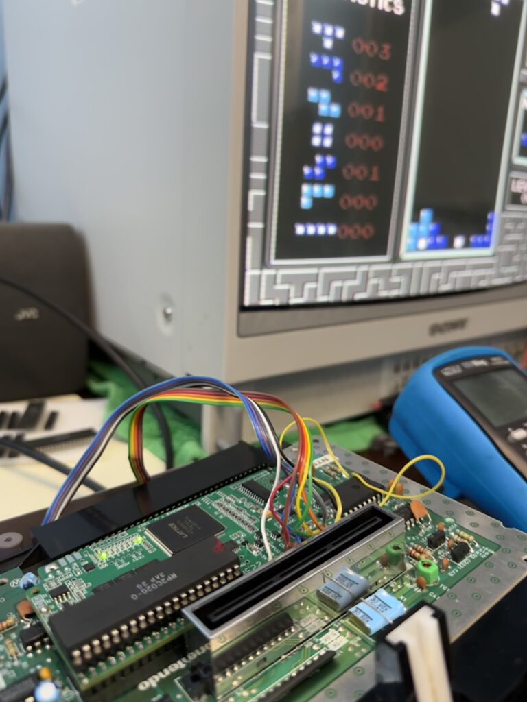
The new PPU tested good when installed directly to the NES mainboard with composite output.
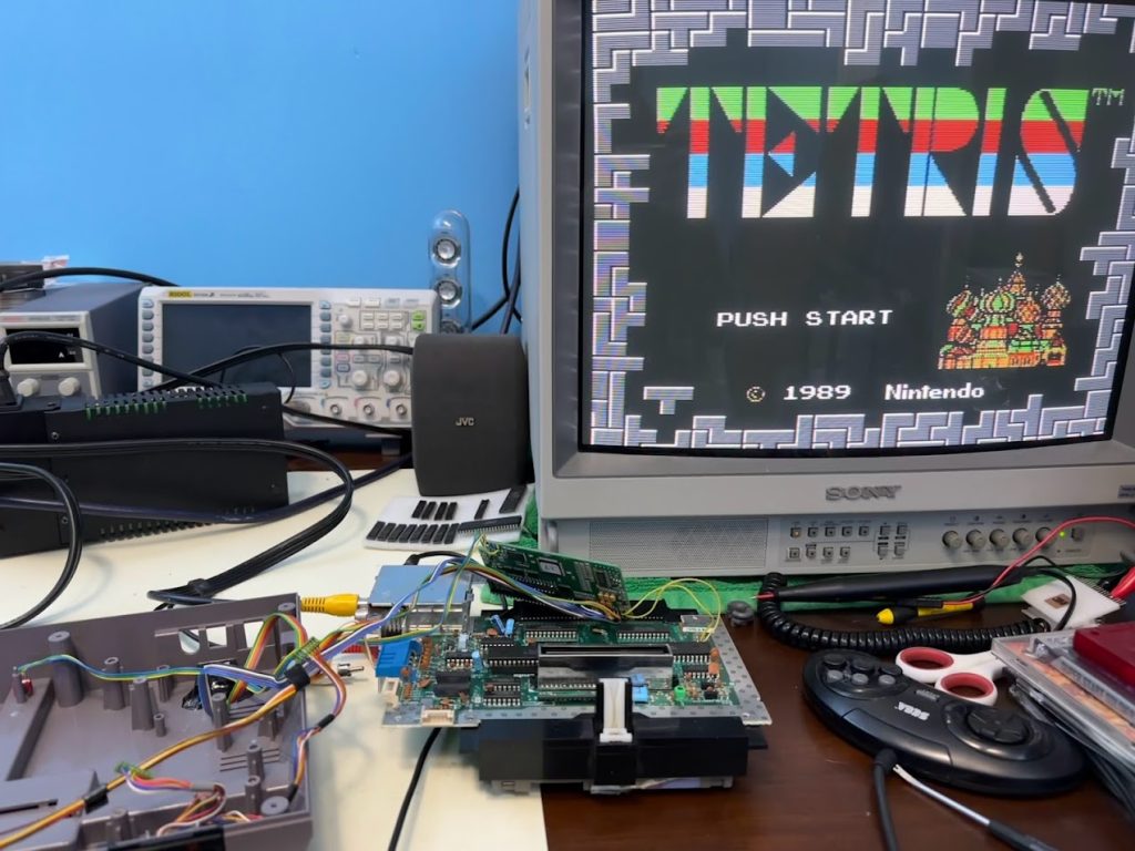
But I still get a black screen when the PPU is installed to the NESRGB. The PPU reads a 5V supply as expected through the NESRGB.
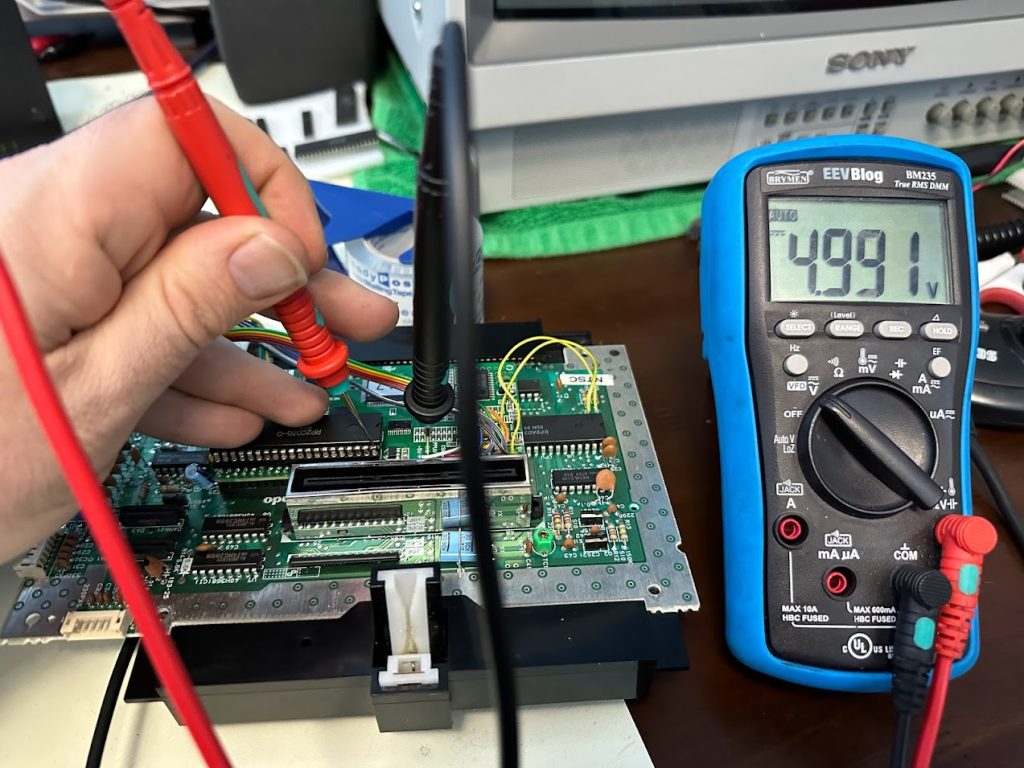
But the NESRGB mod board itself is only reading 1.7V on it’s 5V rail.
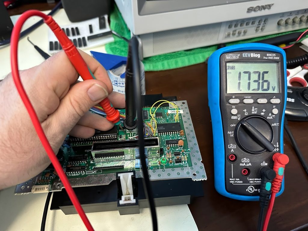
So it seems that the NESRGB mod board itself has damaged components. I’ll reach out to the creator, Tim Worthington, and see if he has any suggestions. Hopefully this NESRGB mod board can be saved. At least the NES and new PPU are good.
Continued…
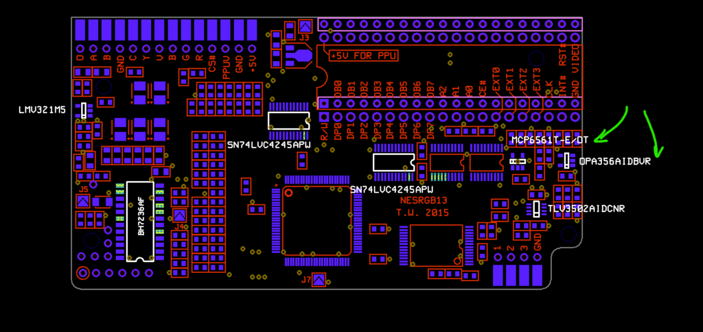
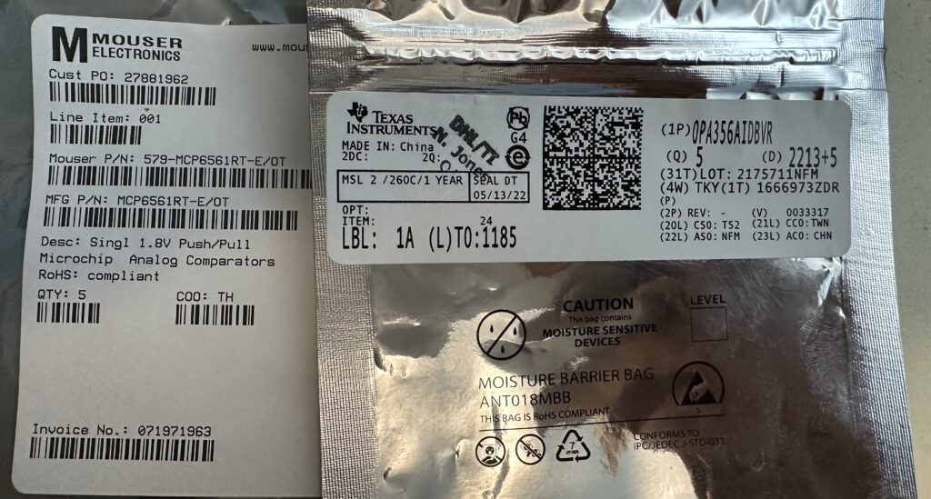
I posted about the failed NESRGB mod on Twitter. The Real Phoenix (@TRG_RetroMods) provided a diagram and highlighted two components that frequently fail when a NESRGB is shorted – MCP6561T and OPA356AIDBVR.
I ordered replacement components which showed up a week later.
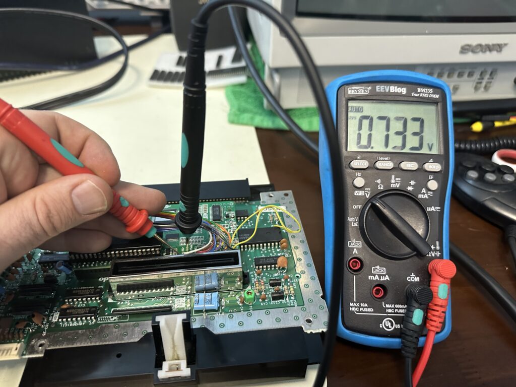
Unfortunately swapping in the two fresh components didn’t revive the NESRGB mod board – it still only output a black screen and the 5V voltage rail on the mod board read low at 0.7V.
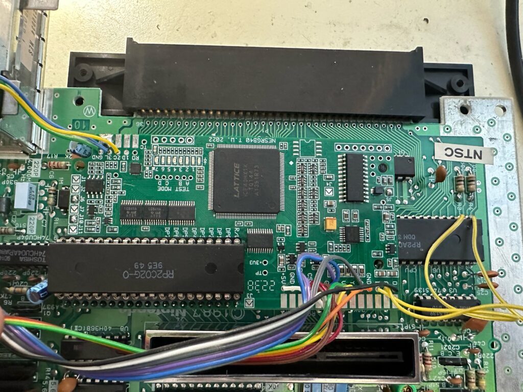
By now, I’d established an email dialog with Tim Worthington, the creator of the NESRGB mod. We both agreed it likely that other components had failed on this NESRGB mod and the best way forward would be to swap in a fresh mod board. Tim sent me a new Rev 4.0 board.
NESRGB Rev 4.0 is largely a drop-in replacement for its predecessor, but I soon found that it requires some additional adjustments for a front-loading NES.
I started off by soldering in the included PPU sockets and pin headers, then swapped the AV Out wiring over from the old NESRGB board. I also set the appropriate jumpers for NTSC, front-loading NES and physical switch control for palette selection.
However, I still did not see any RGB output and the diagnostic LEDs introduced in Rev 4.0 of the NESRGB indicated that there was a warning condition (LED 7) and the NESRGB was disabled (LED 0). The NES was booting the game and outputting a signal on the side composite port at least.
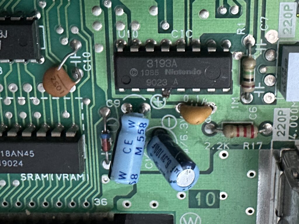
I checked through the NESRGB Rev 4.0 documentation again and found that with a front-loading NES, the 100n ceramic capacitor located at C8 on the NES needs to be replaced with a 220n ceramic cap to address a timing issue with the reset circuit. I replaced the cap accordingly.
Unfortunately this didn’t resolve the problem – they symptoms remained the same. After another dialog with Tim, it turned out an additional modification specific to the front-loading NES and the firmware revision on this NESRGB board was required.
https://etim.net.au/WebHelp/index.htm?context=30
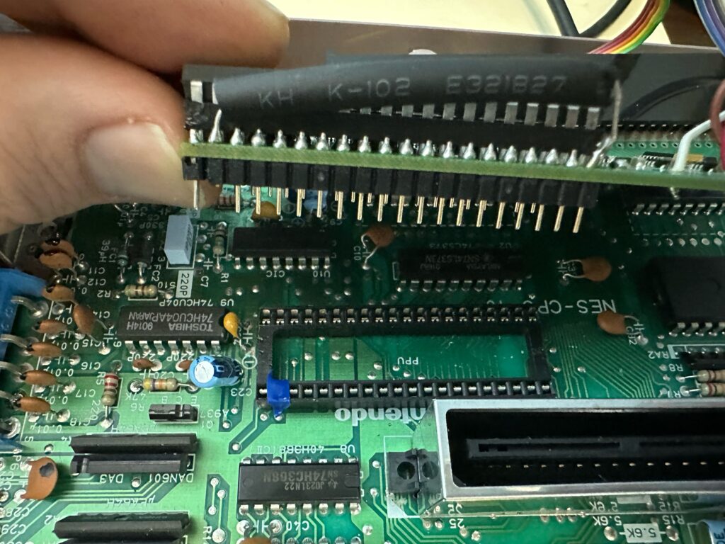
The additional mod calls for clipping header pin 22 from the NESRGB board, covering the receiving pin on the socket with electrical tape, and soldering a 1000 ohm resistor from Pin 22 to Pin 40 on the mod board. I slid a heat shrink tube over the resistor to reduce the likelihood of it shorting against something accidentally (I shrunk the heat shrink and shortened the resistor leads later after confirming that the mod was functional.)
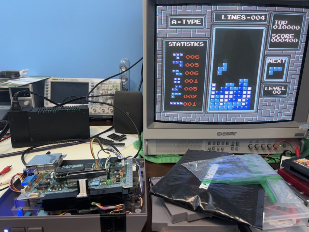
Finally the NESRGB mod spring to life with Palette 3 selected according to the diagnostic LEDs. After one last fix to the Ground line on the AV port, I finally saw clean RGB output on the display.
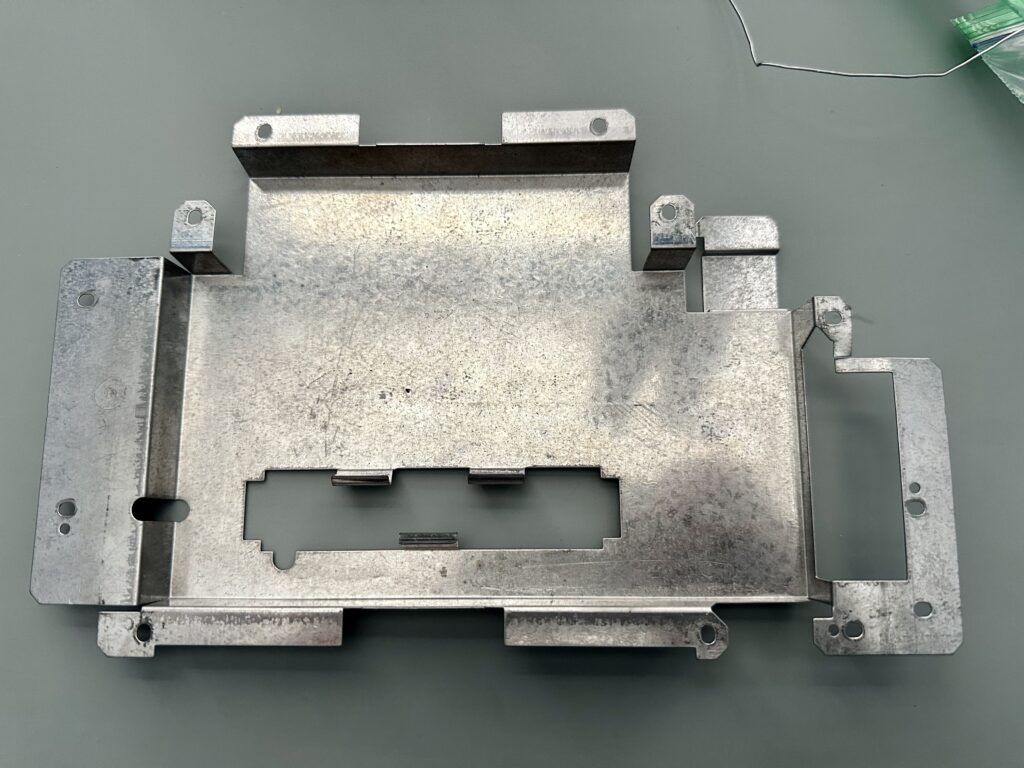
When reassembling the NES console, I noticed that the prior tech had left the lower RF shield in place, and had even run extra long lines for the AV Out port to accommodate the shield. However the added height of the NESRG mod presses the PPU chip right up against the shield. Considering that the shield is also made of thin tin and thus shifts around easily, I strongly suspect that the lower shield was responsible for frying the previous PPU and NESRGB. I left it out this time.
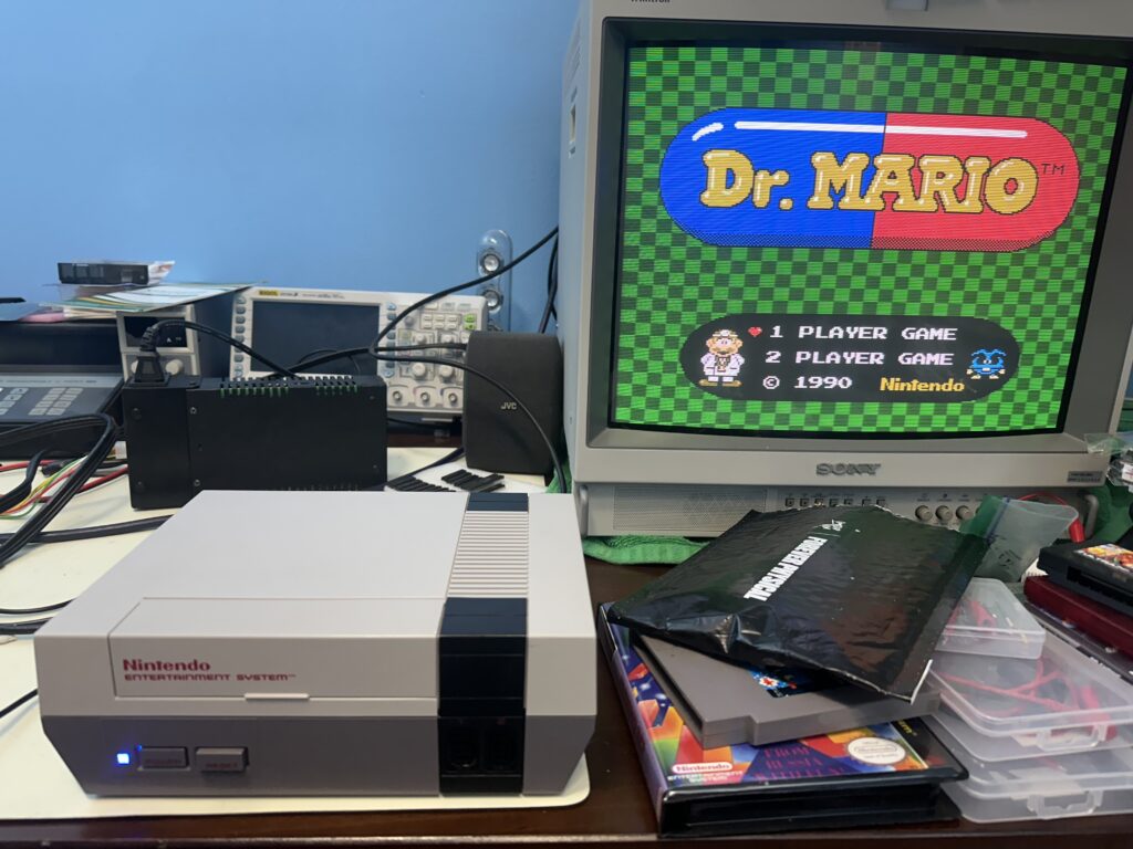
Finally some final testing of the reassembled console. Everything looks good to go – repair successful!