Status: Repaired Successfully Between 4/26/2021 – 6/22/2021
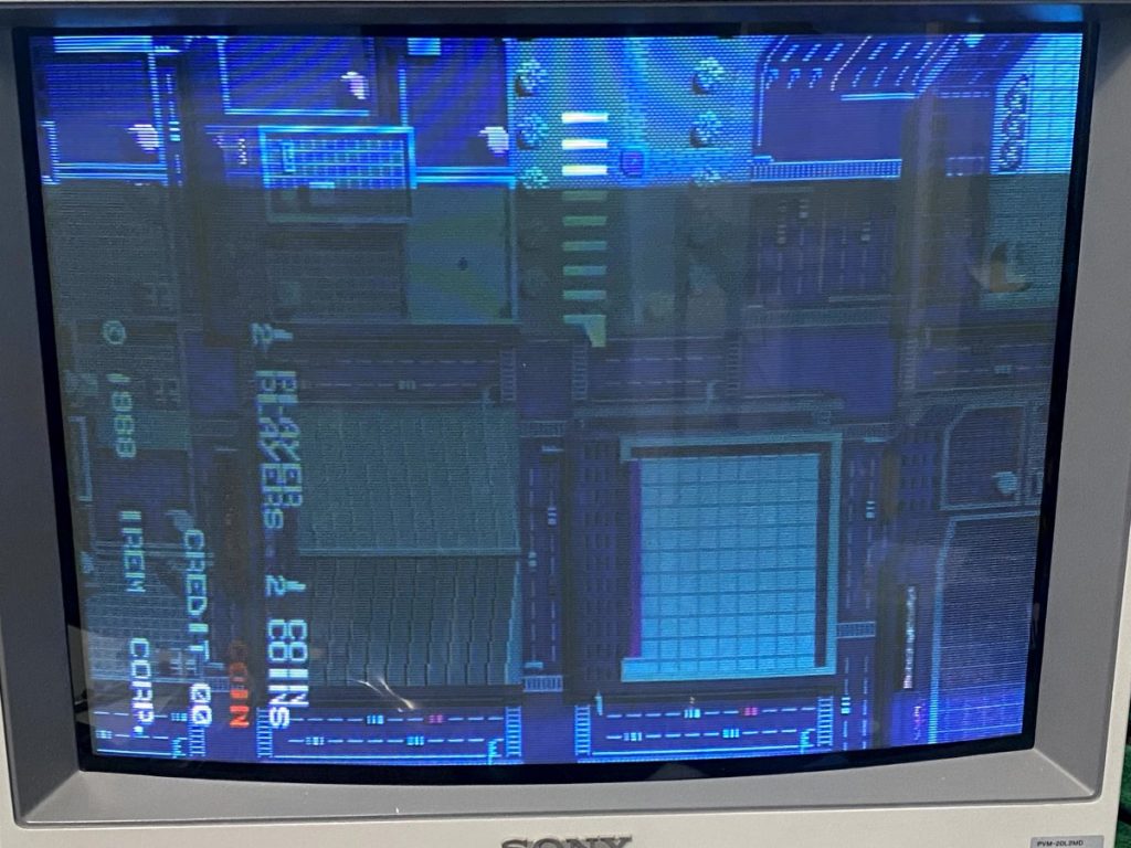
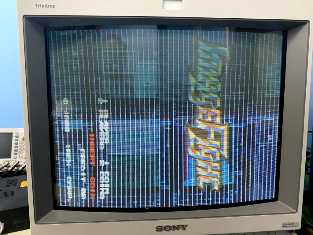
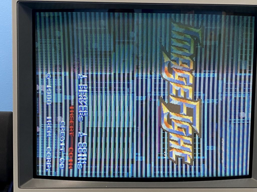
Received for repair this Irem M72 board stack labeled as Legend of Hero Tonma. It would boot to a corrupted screen.
Checking around the EPROMs, I noticed two things immediately:
1) The ROMs and MCU are labeled for Image Fight, not Tonma.
2) Some of the ROMs were installed in the wrong sockets.
Shifting the ROMs around to the correct sockets allowed the board to boot further than before, but it still froze on a corrupted screen.
I dumped all the ROMs and compared them against MAME. All checksums matched the Japanese Image Fight set, except for two chips (L0 and H0) where the checksums didn’t match anything.
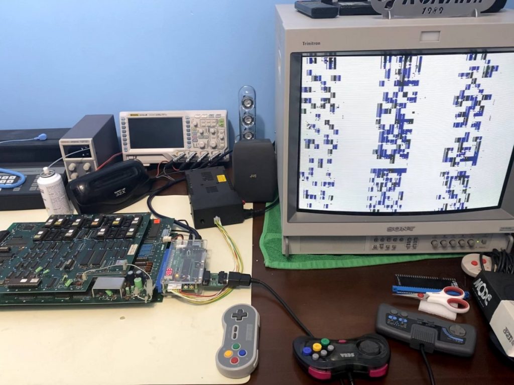
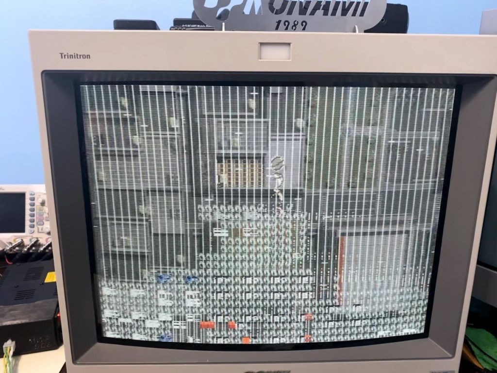
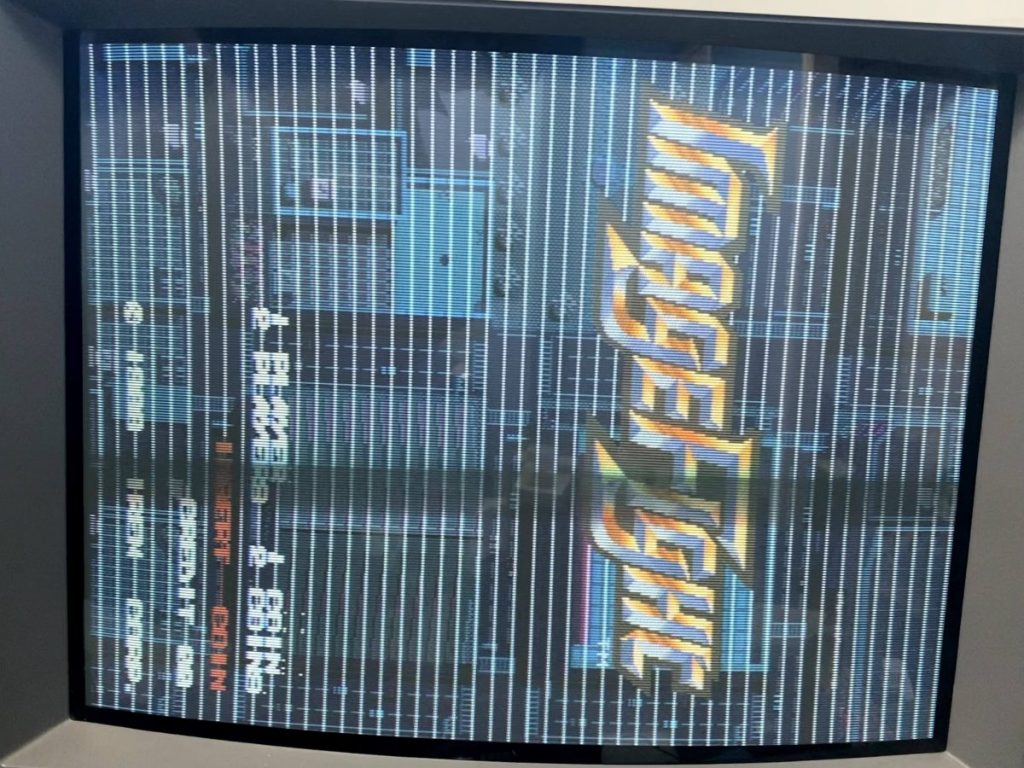
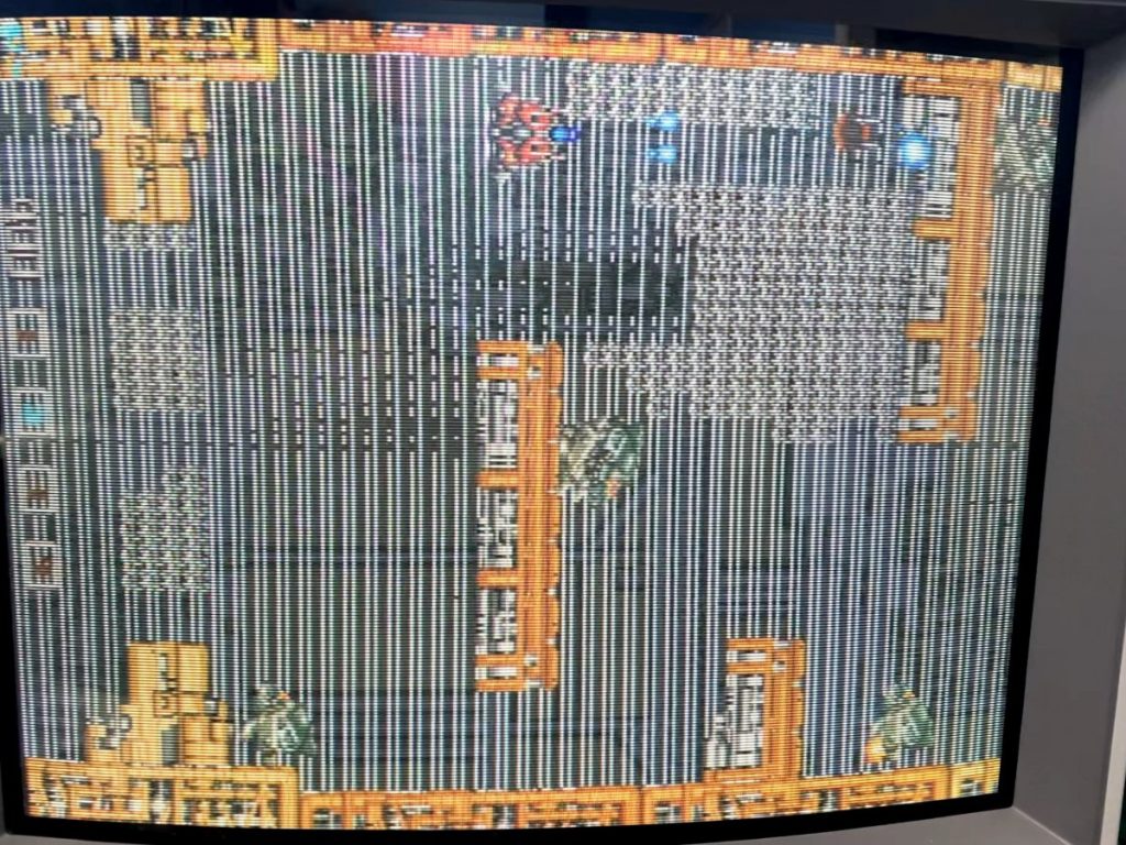
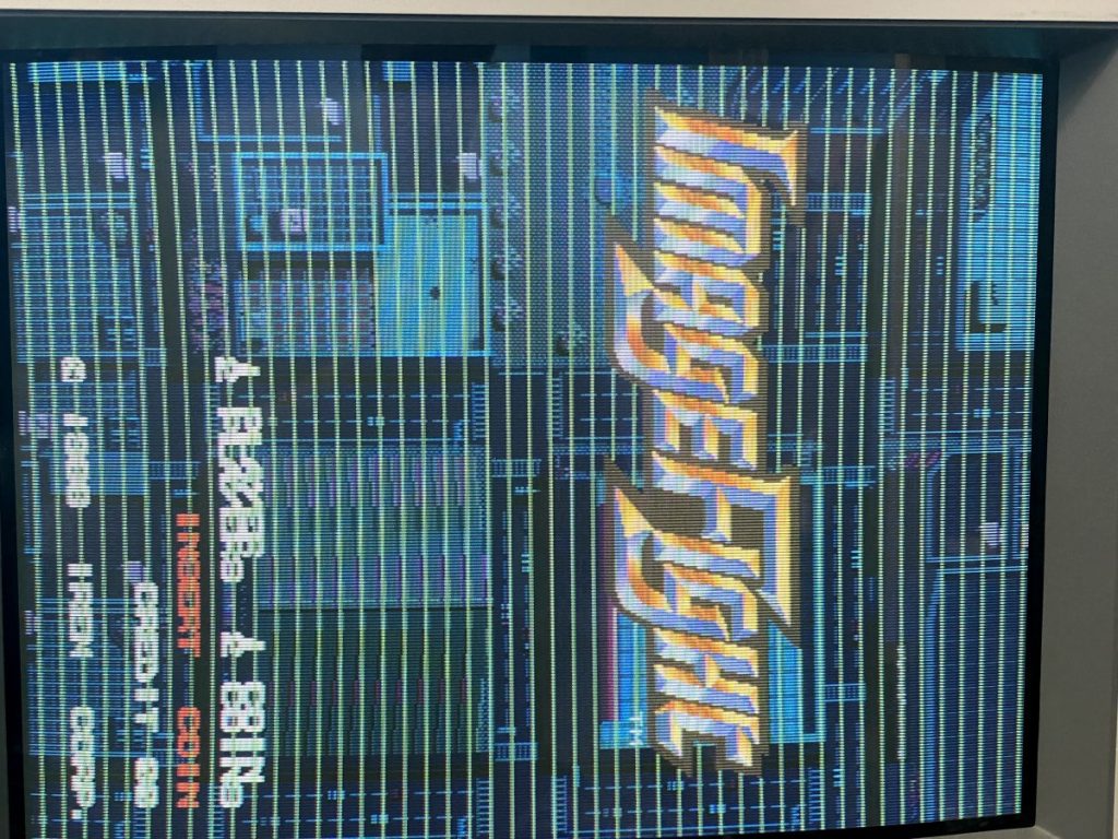
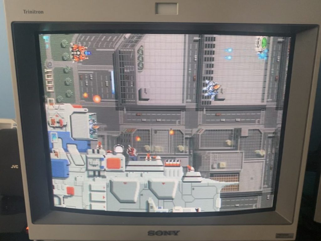
Programming and installing new EPROMs for L0 and H0 now allows the game to boot up and display with an almost completely corrupted sprite layer and jailbars displaying over the top of everything (likely the malfunctioning sprites). Music and sound effects are playing fine.
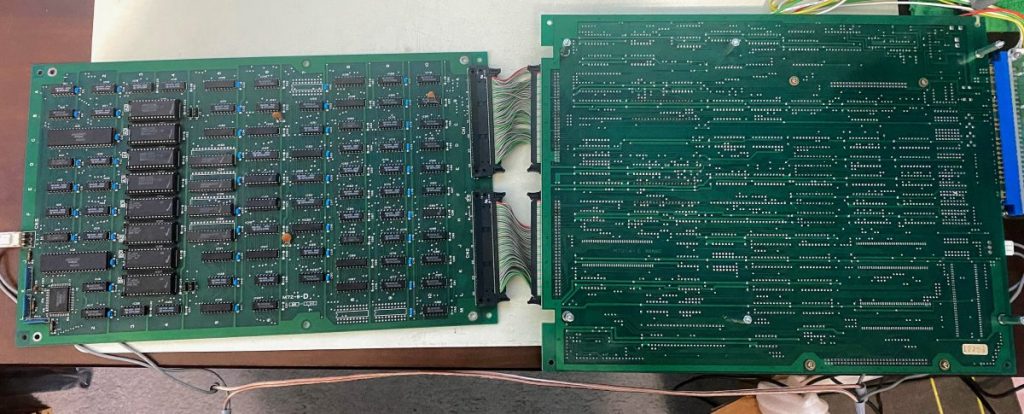
Irem M72 is a three board stack, so I decided to swap around one board at a time with my personal working M72 to narrow down a culprit.
Swapping the middle board brought some of the sprites back, but still no text would show on the title screen or on the board self test.
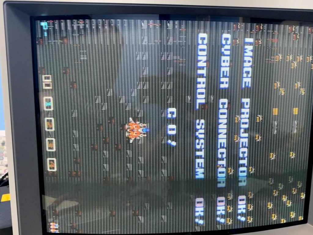
Swapping the bottom board as well brought the game up to what appears to be full functionality, but the self-test shows “ROM NG 1 2”.
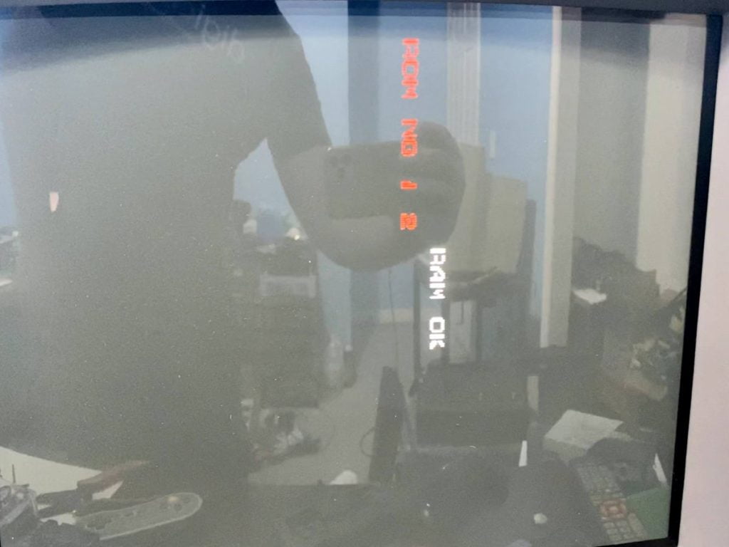
I confirmed before with my chip programmer that the EPROMs were all good, but I’ll try programming and installing a fresh batch next just to be sure. A little Googling also shows that the “ROM NG 1 2” error also appears if the MCU is faulty or is mismatched with the region of the game (ie a World MCU running with a Japan ROM set).
This board will be getting fitted with an M72 Multi so I don’t plan on chasing ROM errors too much unless they show up in the self-test for the Multi as well. In the meantime, there’s faults in both the bottom and middle board to track down next.
I decided to focus on troubleshooting the bottom board first since it draws the text on the self-diagnostic screen, and I like being able to see those results. The self-diag isn’t the best, but it’s definitely better than no diagnostic!
The bottom board has two ribbon cables that connect it to the middle board on the left side, and a small power plug that also connects to the middle board on the right side. I can’t probe the bottom board as-is, but if I rigged some kind of power harness extension for the right side then I’d be able to keep it connected by the ribbon cables, swing it over 180 degrees, and then be able to probe it while it was running.
Before going down that route though, Googling other repair logs for this board set showed that the four SRAM chips fail frequently, and when they do, they cause the jailbar pattern that I’m seeing with it. Following that hunch, I desoldered all four chips from the board.
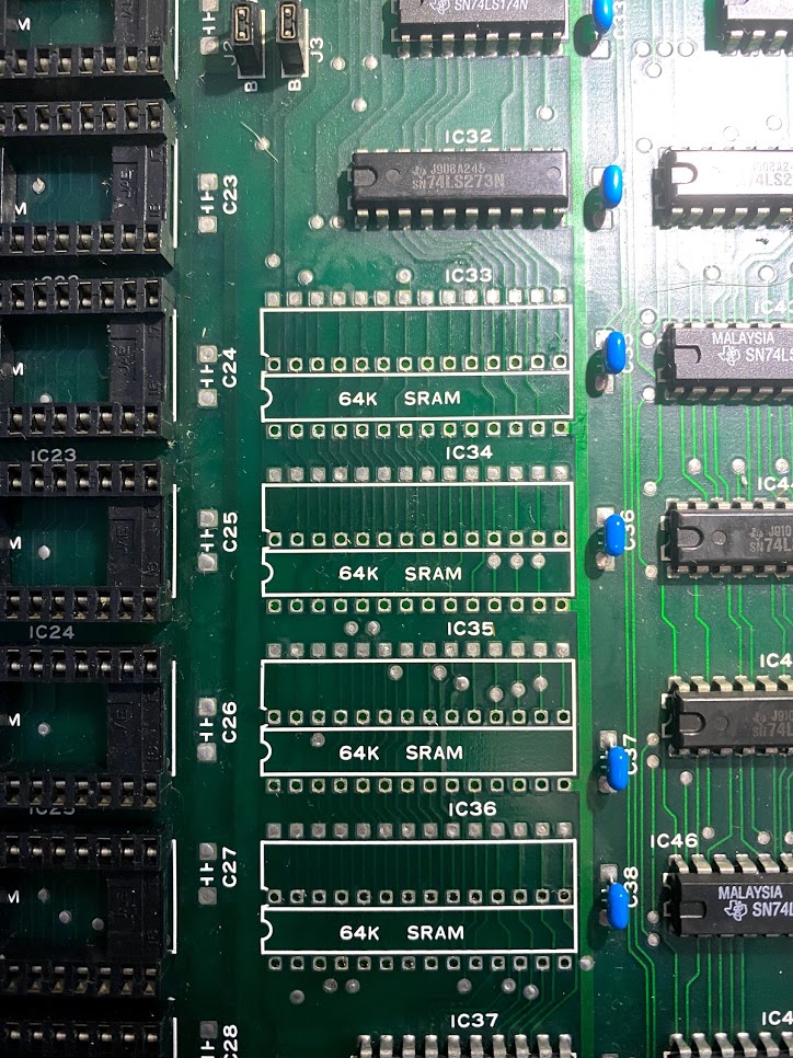
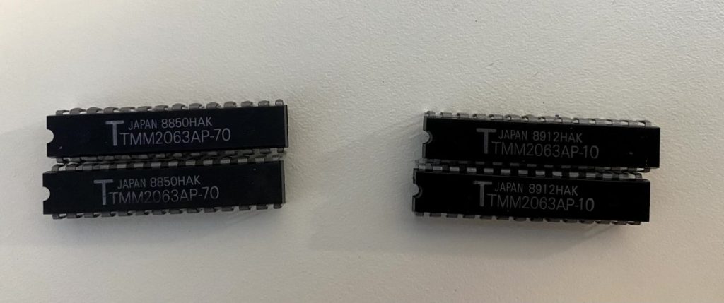
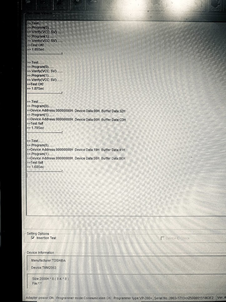
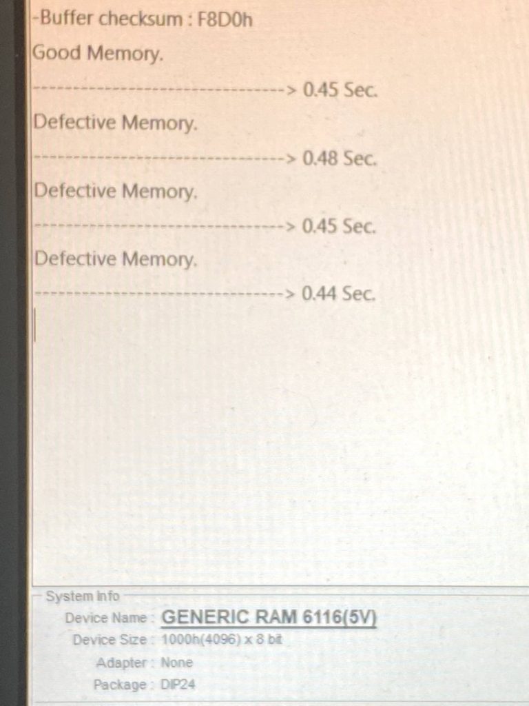
Testing them out of circuit revealed that two of them are bad.
I didn’t have spare SRAM of this type on hand at the time, so I ended up installing sockets into those spots and moved on to troubleshooting the middle board while waiting for parts to arrive.
The middle board drives the sprites. The sprites were glitching so bad that they were almost not being drawn at all – only an occasional “blip” of a sprite would show up occasionally:
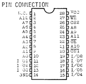
Sprites are driven by some Nanao custom chips on the center board, with ROM data pulled from ROMs C00, C10, C20, C30 on the top board. I’d previously confirmed the Sprite EPROMs had the correct data, so I probed them now with the logic probe to check for stuck lines. They’re 27C010 EPROMs.
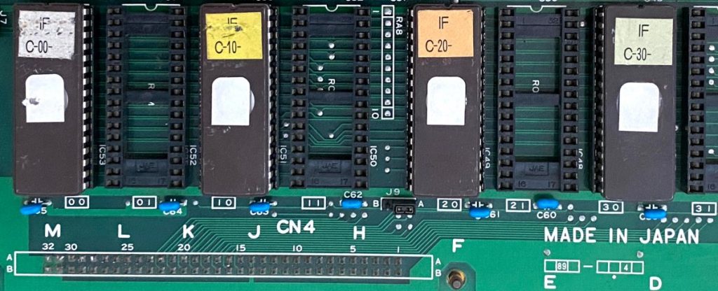
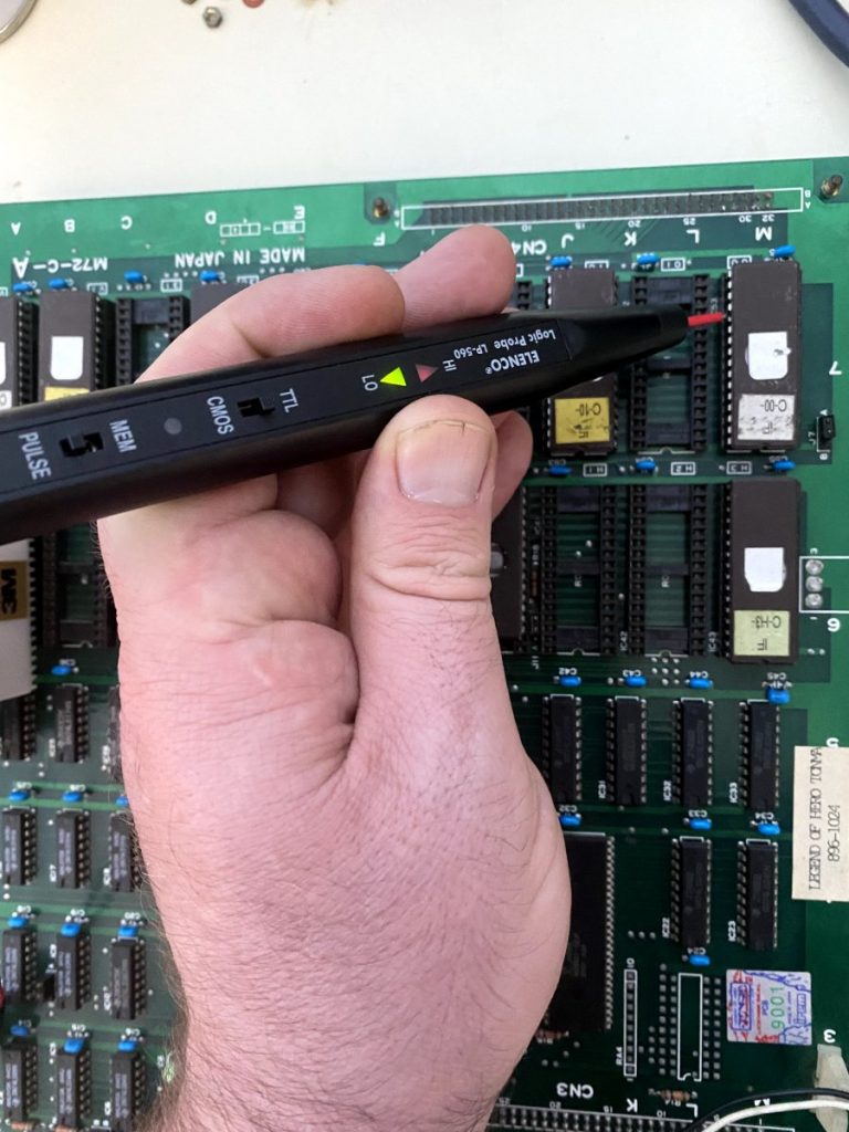
The address, data and control signals all showed expected pulsing activity on all four chips, so I crossed them off the suspect list for the moment.
Looking at the middle board, everything looked to be in good condition with no damaged traces underneath. The top board covers up most of the middle board when the stack is running, so it’s not straightforward to probe it without rigging up something. Before doing that though, I decided to test the sprite RAM. Two out of four static RAM chips on the bottom board had been faulty, and the four Sony CXK5814P-35L RAM chips used as sprite memory have a high rate of failure as well.
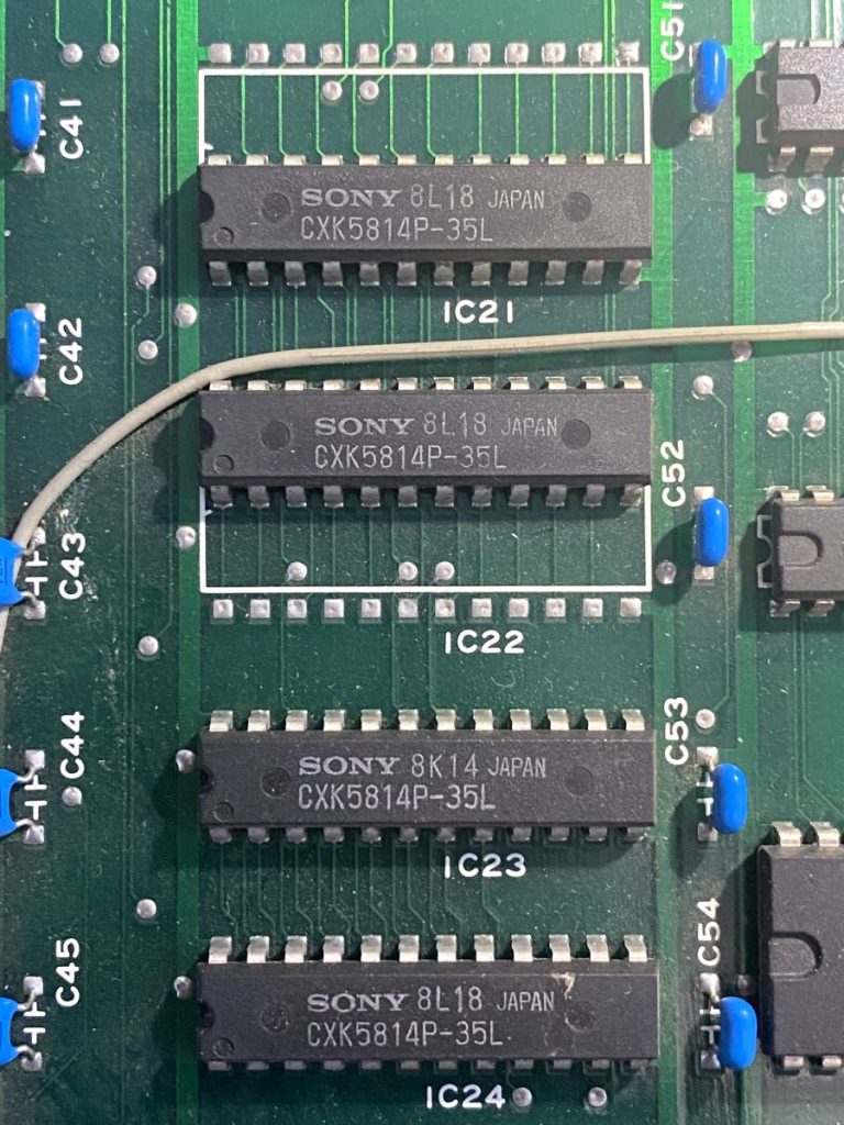
After desoldering and testing, three out of the four of them are bad.
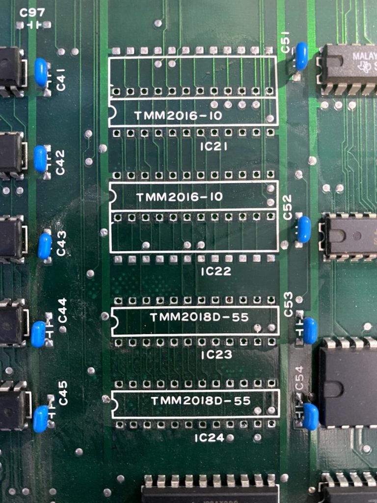
By now, replacement RAM chips had arrived, so I decided to install sockets and replace all four SRAM chips on both boards so that there wouldn’t be a mix of RAM brands and models.
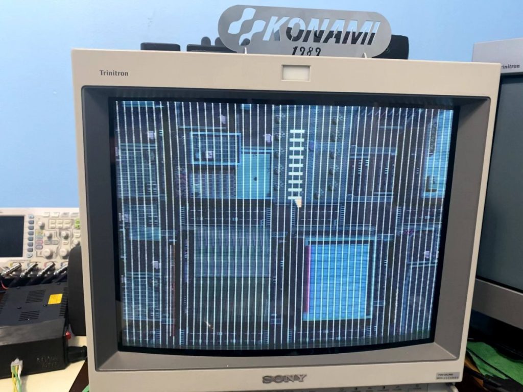
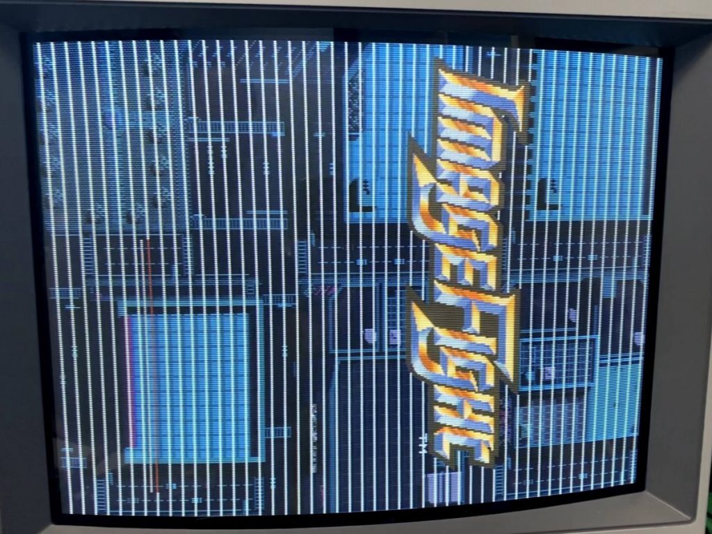
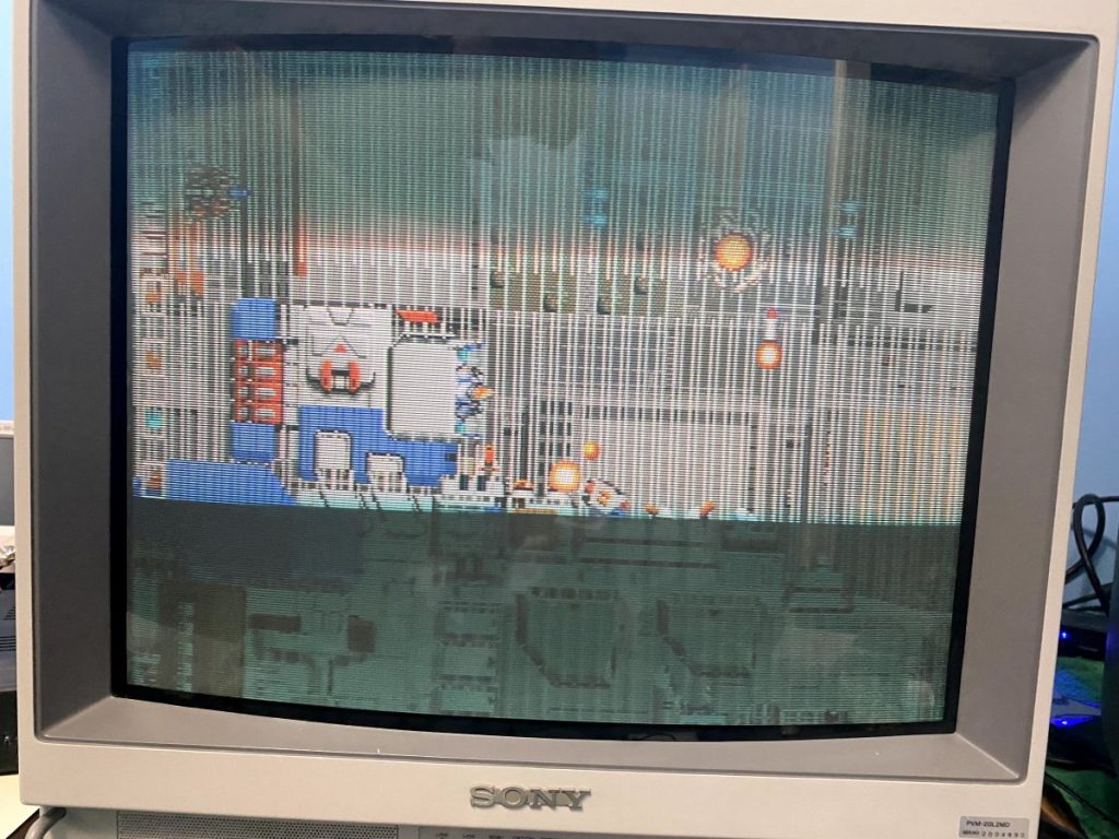
After installing everything and powering up, the sprites are now drawing correctly, but the backgrounds still have vertical jailbar lines. It’s not over yet…
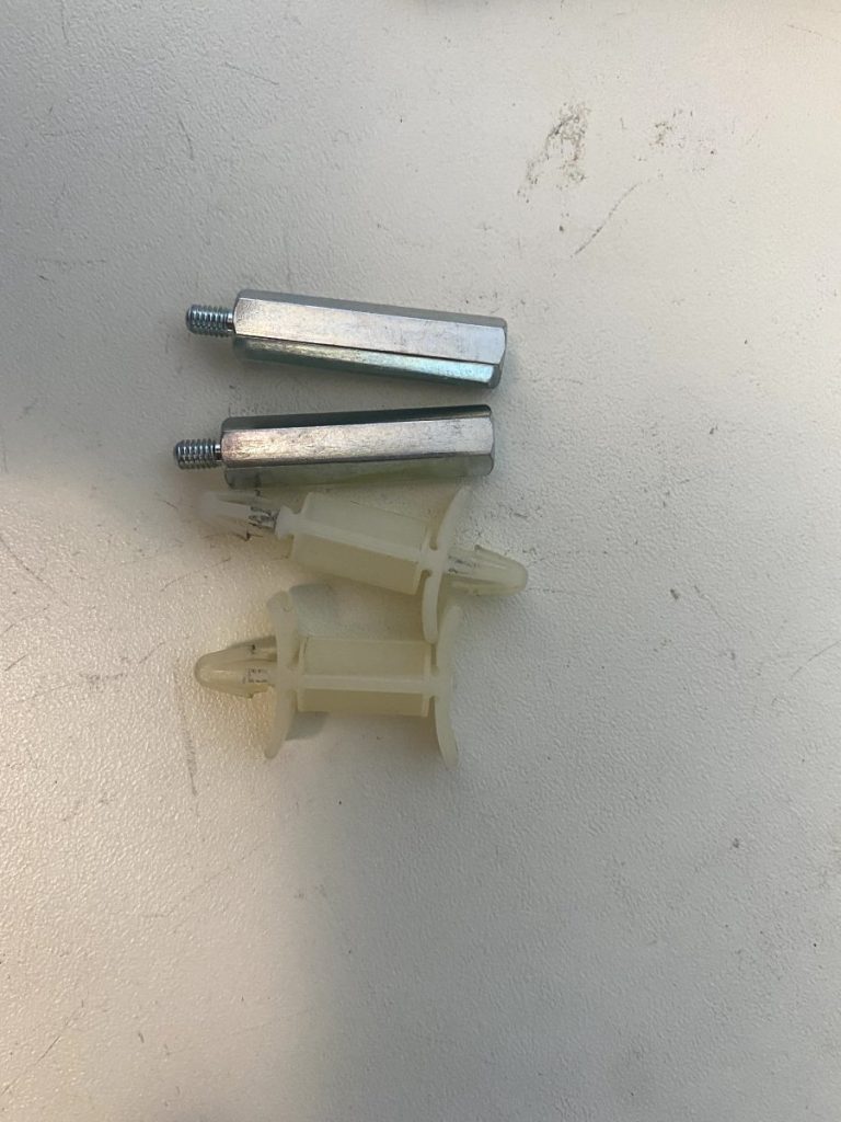
Backgrounds are handled by the bottom board, so I needed to work out a solution for probing the bottom board with my logic probe. The bottom board is secured to the middle board with plastic standoffs, which aren’t very sturdy to begin with, and some of the standoffs were broken or missing with this set, making them even more precarious. So first, I replaced the plastic standoffs with metal ones to stabilize the stack.
And once the stack was sturdy, I turned the stack on its side and propped it up with some solid anti-static foam and a book.
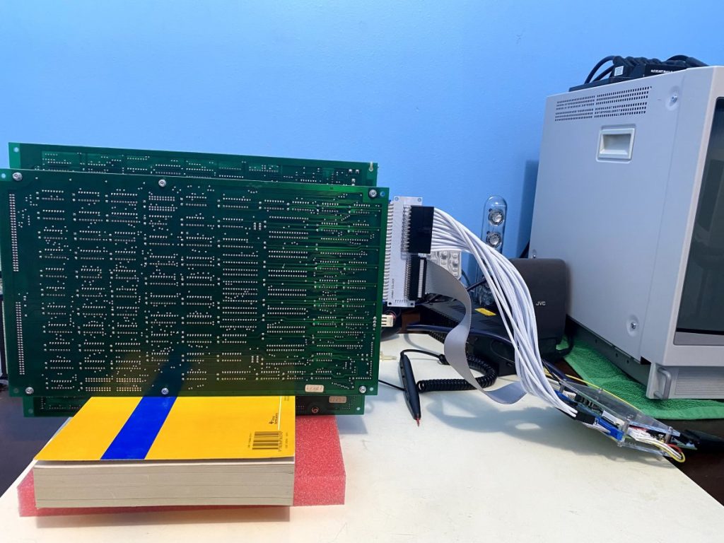
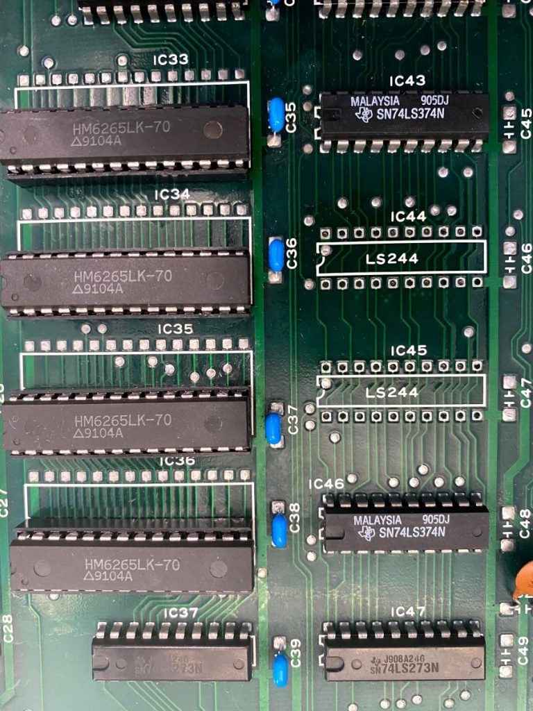
Now I could safely probe the bottom board from underneath. Checking around the RAM lines, I noticed that I/O 5, 6, and 7 on the middle two RAM chips (IC 34 and 35) never showed any activity. NOTE that a few other IO lines only showed activity at certain times in the demo loop, like when a secondary cloud layer was being drawn.
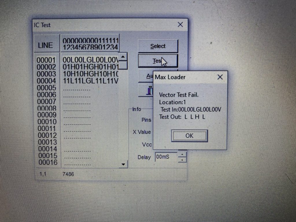
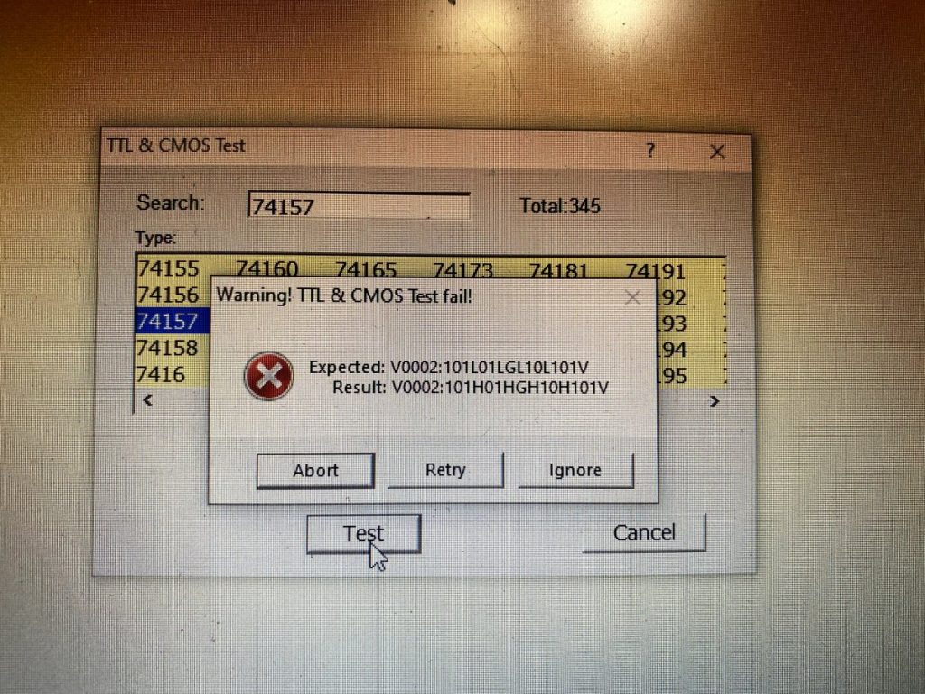
I traced those I/O lines back to two adjacent 74LS244 Octal Line Buffer chips at IC 44 and 45. Probing on those TTLs confirmed that the outputs for those lines were dead when they should have been triggering (confirmed with the truth table in their datasheet), so I removed both of them. They both tested bad out of circuit.
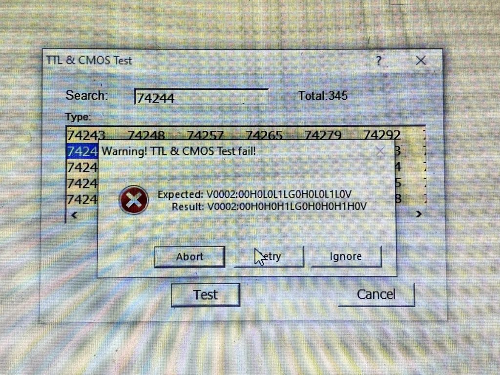
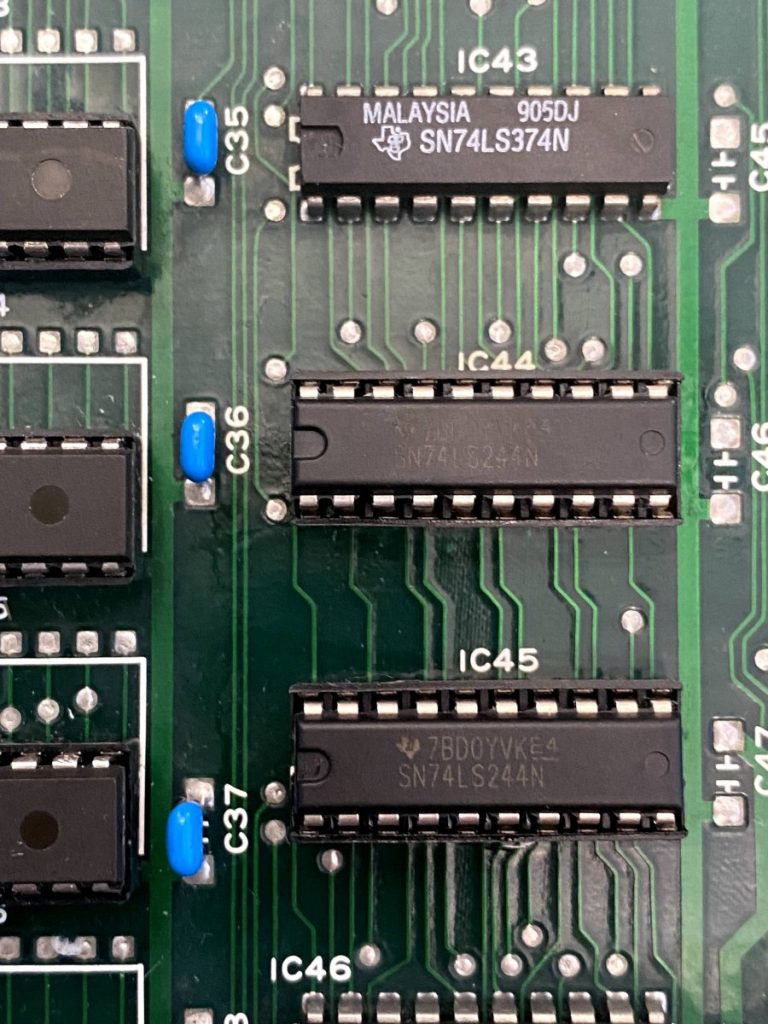
This time I had replacement TTL parts already on hand, so I installed sockets, confirmed that the new parts were good on the tester, and installed them.
I was feeling pretty good about things at this point, but unfortunately after powering on the background jailbars are still the same:
For the next round of M72 troubleshooting, I decided to try a procedure I really should have done earlier – logic probe the behavior of the SRAM and custom chips on my good bottom board and compare the behavior of the bad bottom board against it.
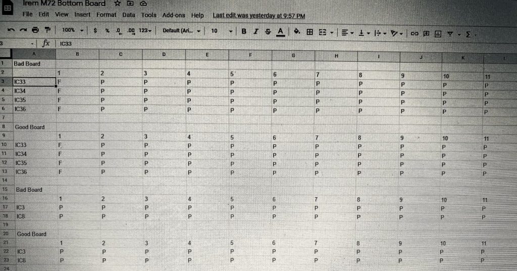
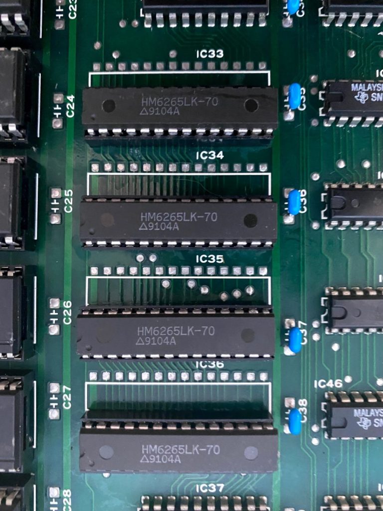
This highlighted a difference in the behavior of Pin 22 of two SRAM chips – IC 33 and 34. Pin 22 is the Output Enable line and it is shared between the two chips. The line is Active High, and the good board was holding it low most of the time with the occasional pulse high (LPH) while on the bad board, the line was heavily pulsing frequently (P). Thus, both chips were engaging more often then they should be – that could cause jailbars to be drawn, right?!
So where does the Pin 22 signal originate from? It turns out that it comes from Pin 8 on IC84 – a 74LS86 TTL chip way over on the far right side of the board next to the ribbon cables. I desoldered it and it tested bad out of circuit.
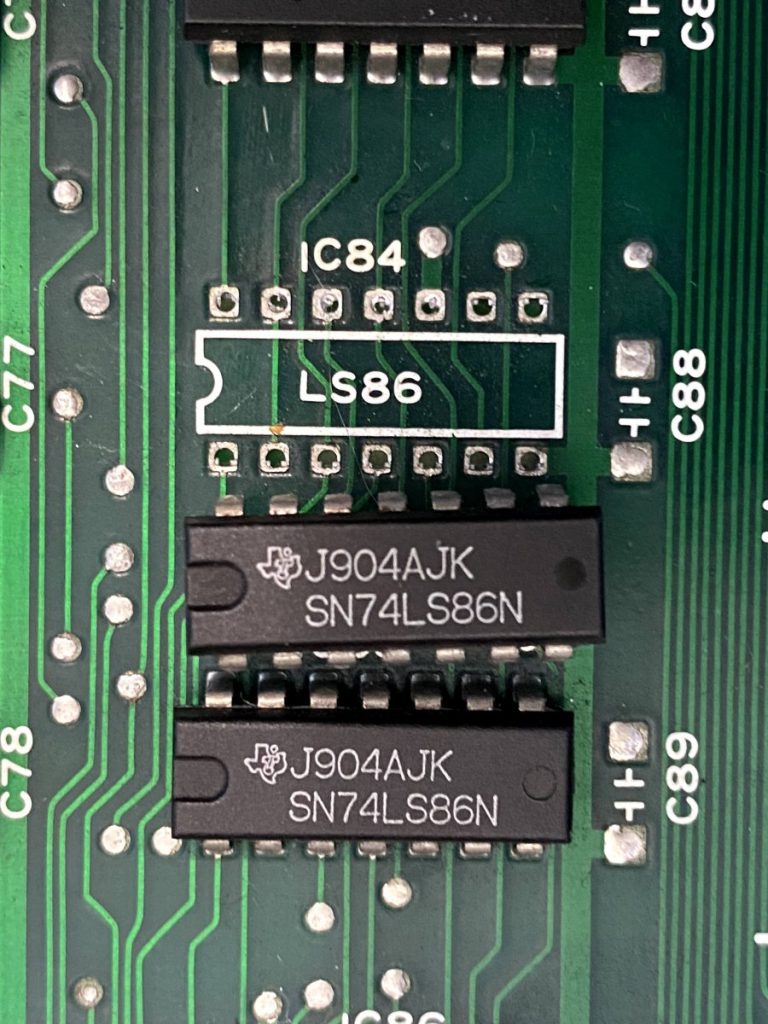
However, after installing a replacement, the jailbars were STILL present. I checked the logic behavior afterward and all of the SRAM logic behavior now matches the good board – Pin 22 is now being LPH enabled as it should be. Now the logic probe behavior appears the same between the two boards.
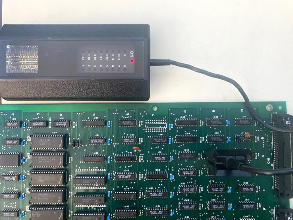
For the next round of bottom board troubleshooting, I rigged up a way to allow me to probe the bottom board from the top side while it is connected and running – I flipped the A & B boards upside down and ran a extended power line between them.
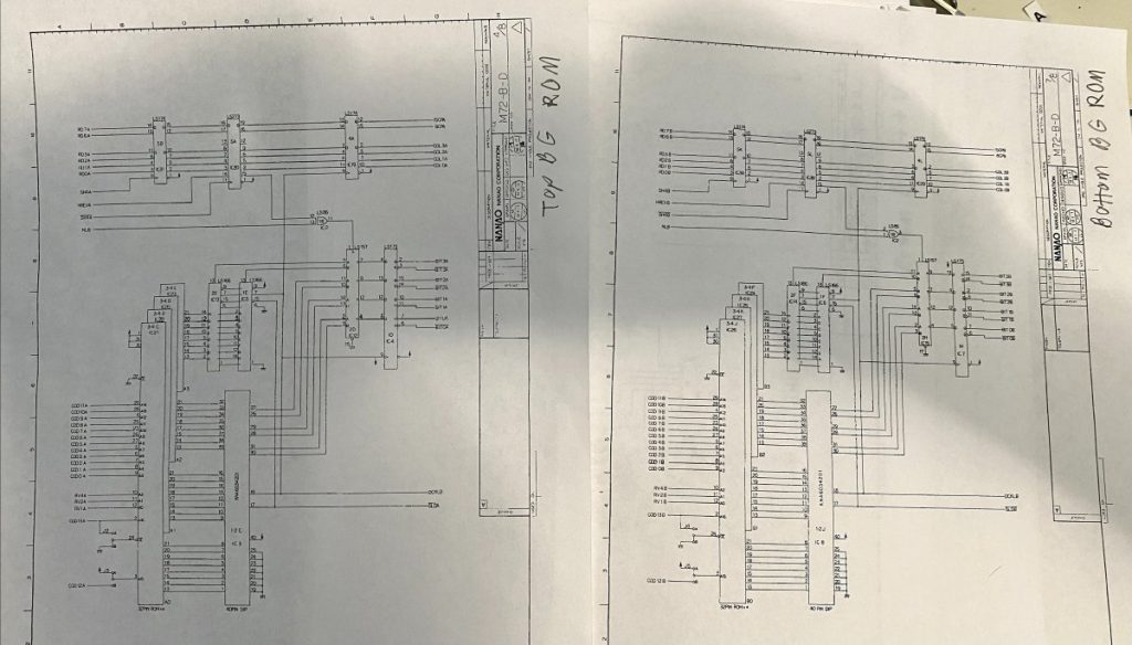
This allowed me to check things much more easily – I could now use my HP Logic Comparator to quickly verify the smaller TTLs as the game was running. I also printed out the relative sections of the schematics – R-Type has schematics widely available and although its top board is missing sound sample hardware that’s in all the other M72 games, the bottom board is the same. I also switched from using the logic probe to the oscilloscope so I could detect TTL output line issues where they are pulsing, but not at the proper voltage thresholds.
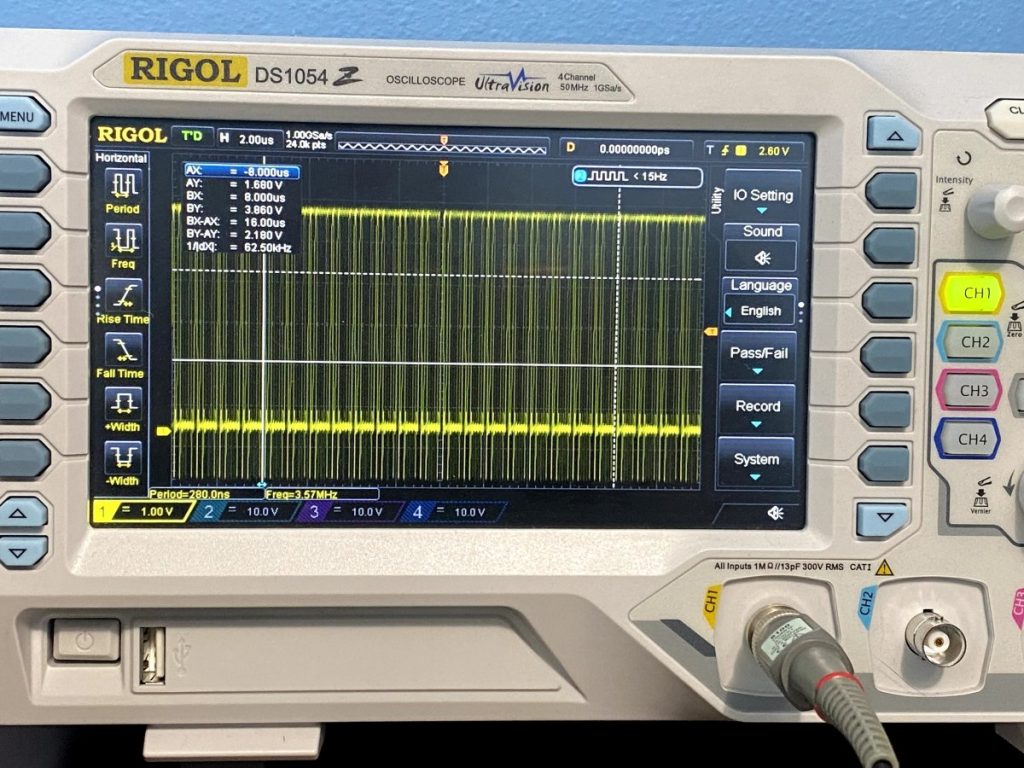
Between the schematics, comparator and the oscilloscope, I identified three more malfunctioning TTLs – IC 1, IC 12 and IC 59. All three had weak outputs and tested bad out-of-circuit.
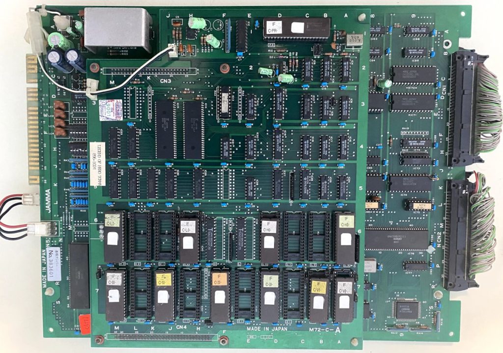
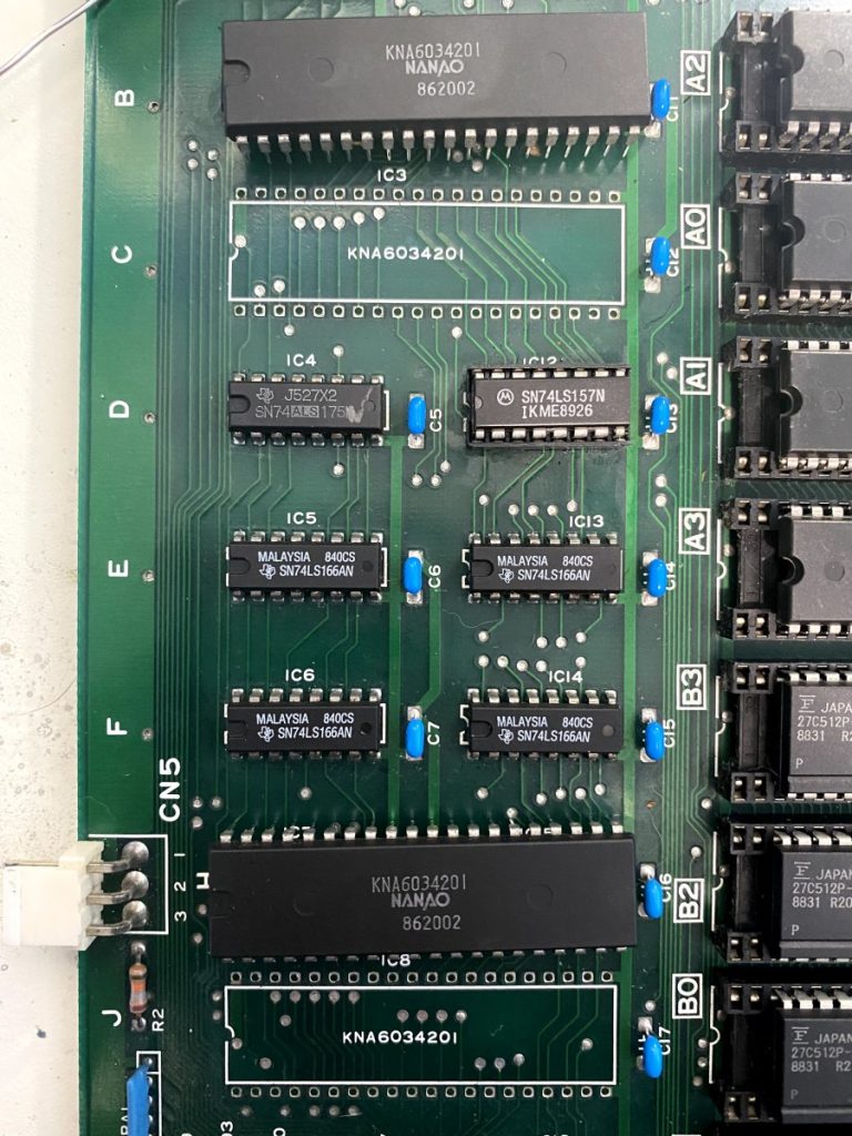
Replacing those TTLs cleared up a few tile rendering glitches I’d noticed in the background, but still didn’t address the obvious jailbars. Everything kept pointing back to the two KNA6034201 customs on the left side of the board.
The M72 has two background tile generators, and the bottom board is essentially split horizontally across the center where the top half is all the circuitry for one generator while the bottom half is all the circuitry for the second generator. The two circuits are pretty much mirror images of each other. CPU Address, Data and Clock lines come in from the middle board over the edge ribbon connectors, and these signals are shared on both tile rendering circuits, with Chip Enabling lines determining which is activate at any given time.
The final step of the tile rendering for each board half is when the KNA6034201 custom streams graphics data in parallel from the four ROMs, then pushes data out serially through two TTL chips out to the KNA91H1014 SMD Pallette Custom in the lower-left corner – one of the few chips on this board that is shared and not mirrored.
Both KNA6034201 customs appeared healthy – I was detecting active signals on all the input and output lines. However, I was becoming convinced that one or more of the inputs may not be getting “mixed” correctly internally. I decided to remove both KNA6034201 customs, install sockets, and swap them around. If the jailbar appearance and behavior changed just by swapping the two customs around then I’d know that one or both of them were faulty.
Swapping around the two customs made a difference alright – it DOUBLED up the number of displayed jailbars!
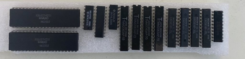
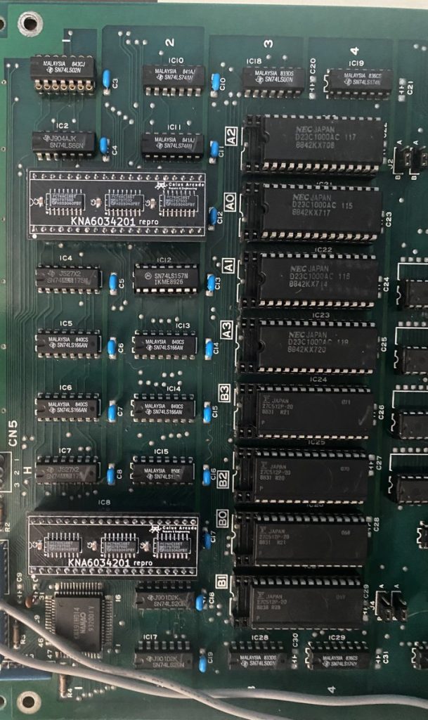
I’m forced to conclude that one and possibly both KNA6034201 customs have failed internally. Fortunately, Caius of Caius Arcade Repairs & Engineering has reproduced them: https://caiusarcade.blogspot.com/p/reproductions.html
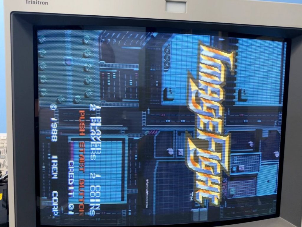
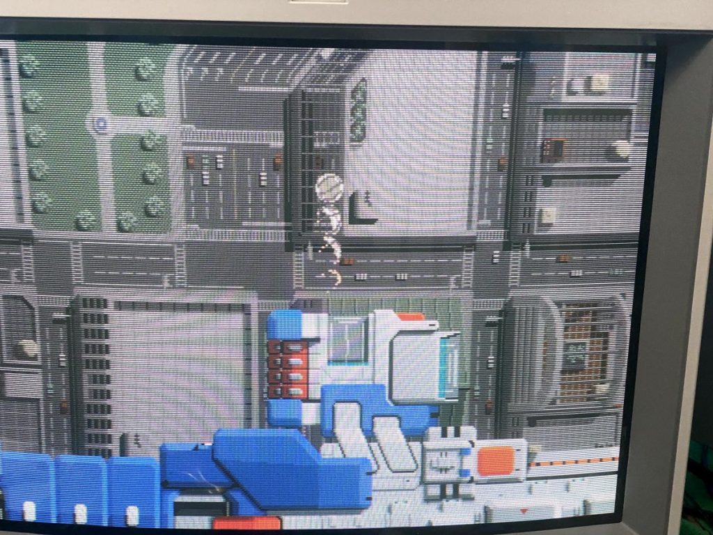
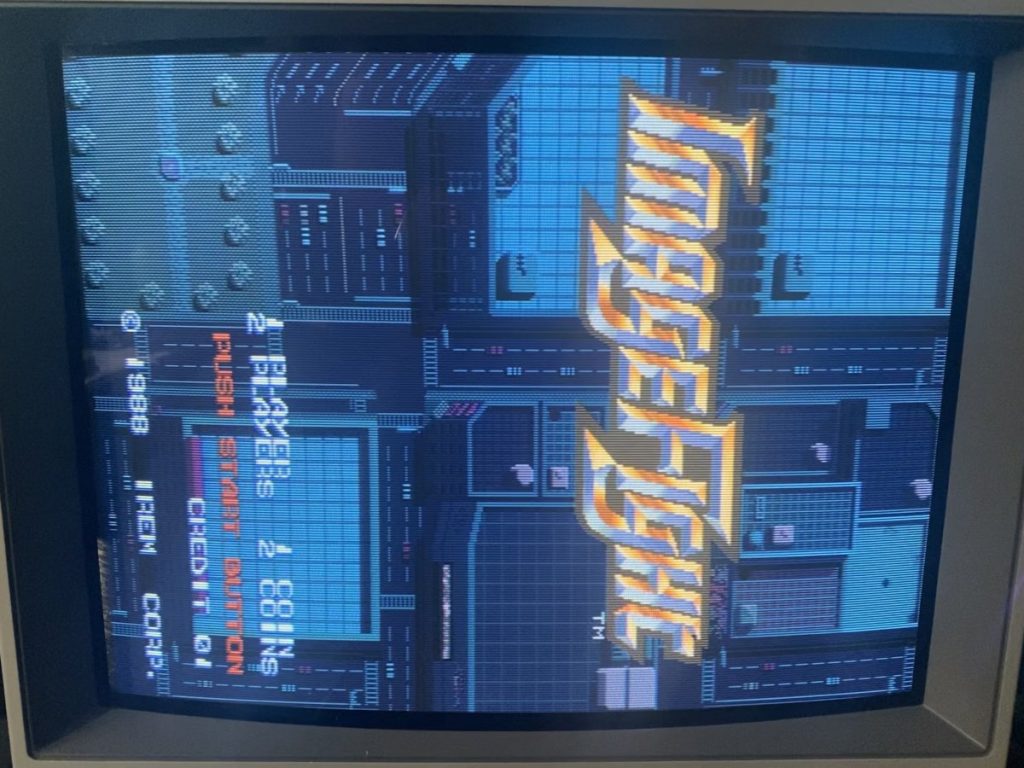
I ordered in two KNA6034201 reproductions, installed them and FINALLY the board set worked 100% with no jailbars!
I ran the board for 24 hours as a “soak test” just to make sure that everything was solid. For good measure, I tried swapping in each of the original KN customs one at a time just to see if one of them was good, but unfortunately both custom chips have issues.
In the end, I ended up replacing 14 failed chips across both the middle and bottom boards.